 EN

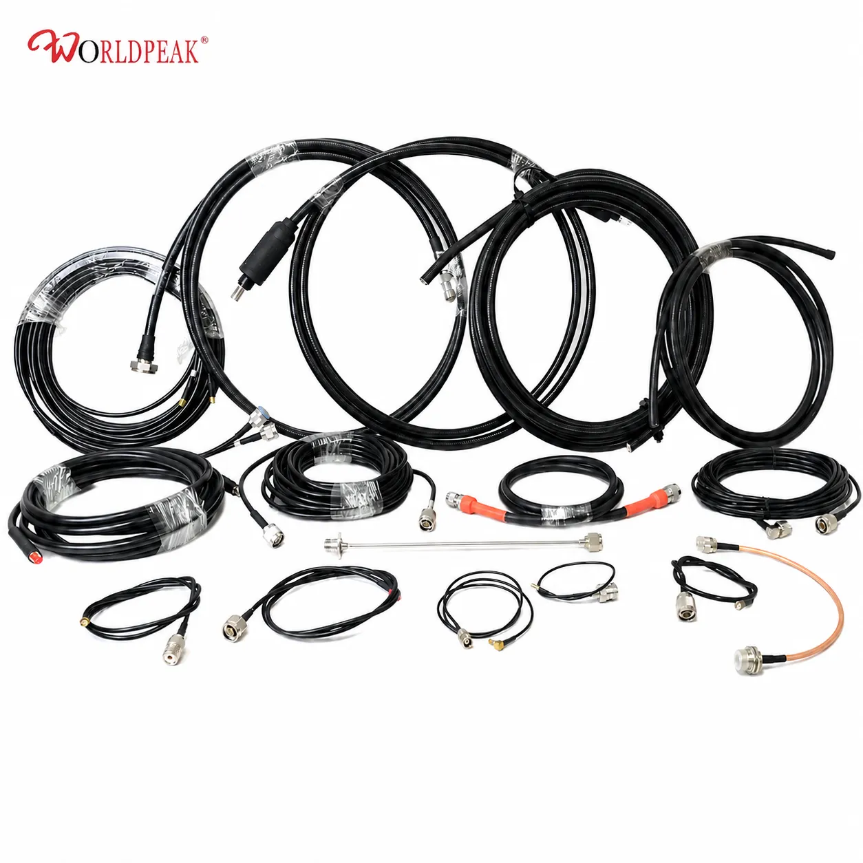
Waterproof Coaxial Cable Assembly: IP67 Solutions
For an outdoor RF link, a waterproof coaxial cable assembly is more than a cable with a sealed boot. It is a controlled transmission line whose center conductor, dielectric, shield, jacket, connector interface, and installation method must work together. Procurement teams get better results when they check electrical compatibility and sealing details at the same time.
This guide explains how to assess an IP67-oriented assembly for antenna, sensor, radio, industrial, and field-installation work. The practical goal is simple: keep moisture away from the critical interface without creating avoidable loss, mismatch, or mechanical stress.
Start with the cable construction, not the IP label
A coaxial cable carries its signal on a center conductor surrounded by an insulating dielectric and an outer conductor or shield. The geometry of those layers establishes impedance; the conductor and dielectric materials influence attenuation; and the shield helps contain the RF field while reducing susceptibility to external interference. A waterproof coaxial cable assembly must preserve that geometry right through the terminated ends.
IP67 is useful shorthand for an enclosure-style ingress test involving dust protection and temporary immersion. It is not, by itself, a guarantee of frequency range, insertion loss, UV life, cable flexibility, or connector mating quality. Ask what part of the assembly is protected: the cable jacket, the connector-to-panel interface, the mated connector pair, or an added backshell and seal.
The interface is often the weak point
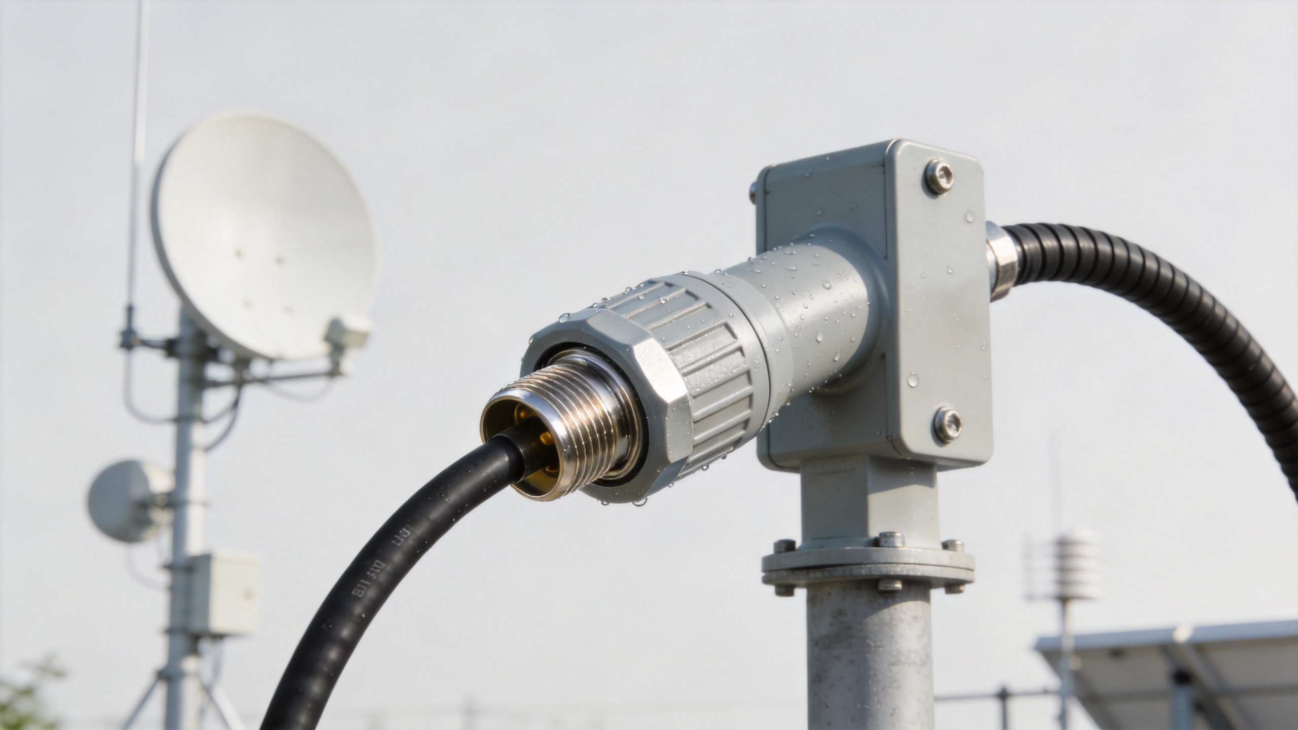
A correctly selected coax plug needs the right interface family, cable fit, termination method, and gasket or O-ring arrangement where applicable. A large cable forced into an undersized rear entry can distort the dielectric; an unsealed mating face can still admit water even if the jacket is outdoor rated. Request the mating condition and assembly drawing before treating an IP rating as applicable to your installation.
Impedance: choose 50Ω or 75Ω for the system
Impedance selection should follow the equipment, not a general preference. A 50Ω assembly is common in RF communications, wireless infrastructure, test, and many antenna-feed applications. A 75Ω assembly is often associated with video, broadcast, and distribution systems. Mixing them can introduce a mismatch that degrades return loss and can affect system behavior, especially as frequency rises.
| Selection point | 50Ω route | 75Ω route |
|---|---|---|
| Typical use | RF radios, antennas, wireless and test interconnects | Video, broadcast and signal-distribution systems |
| Buyer check | Confirm radio, antenna, connector and cable are 50Ω | Confirm source, distribution hardware and connectors are 75Ω |
| Waterproof focus | Verify the mated interface and outdoor seal | Verify the mated interface and outdoor seal |
The waterproof requirement does not change this rule. First match impedance, then choose the cable size, connector form, and sealing arrangement that fit the environment.
Attenuation, shielding, and cable size
Longer runs and higher frequencies make attenuation more important. A larger, lower-loss feeder construction can be appropriate where a rooftop or mast installation needs margin over a meaningful run length. A compact cable can be easier to route inside an enclosure or around moving equipment, but it may not be the right trade for every distance and frequency. Compare published attenuation at your operating frequency rather than relying only on a family name.
Shield construction matters as well. A well-executed braid, foil, or combined shield supports signal containment and helps reduce coupling from nearby equipment. Yet shielding cannot compensate for a poor termination. Specify the cable type and termination process together, then confirm electrical test expectations such as continuity, insertion loss, and VSWR where they are relevant to the project.
For lower-loss 50Ω feeder planning, review the available LMR400 Low-Loss 50 Ohm Coaxial Cable record alongside the required connector and installation geometry. For a pre-terminated option, the confirmed product record for Worldpeak SS402 Pre-Terminated Cable Assembly can help start a configuration discussion. These links identify available product records; final suitability still depends on the confirmed application specification.
Where RG58-family cable fits
RG58-family cable is commonly considered where routing flexibility and compact handling matter. Terms such as rg58 kabel and rg58c u appear in sourcing requests, but they should trigger a specification check rather than an assumption that all constructions are equivalent. Confirm impedance, conductor construction, jacket material, operating frequency, run length, and the exact connector termination before release.
For indoor cabinet links, short bench connections, and protected routing, a smaller cable may be a practical choice when its loss and power limits meet the design. For outdoor cable runs, select the jacket and interface seal for UV exposure, moisture, temperature cycling, and physical support. If a run carries lower-level signals over distance, a larger low-loss cable may be the more economical system decision even when the initial assembly cost is higher.
Installation controls that protect the assembly
- Keep the bend radius generous. Use the cable manufacturer’s specified minimum bend radius; do not kink the cable or bend it tightly at the connector rear.
- Manage strain. Support the cable so its weight and wind movement do not pull on the connector or sealing hardware.
- Seal clean, dry interfaces. Inspect threads, gaskets, and mating faces before assembly. A seal cannot correct contamination or a damaged connector.
- Plan drip paths. Route outdoor sections so water does not collect around a connector entry or follow the cable directly into an enclosure.
- Document the configuration. Record impedance, cable family, connector gender, length, ingress requirement, and required electrical checks on the purchase order.
Frequently Asked Questions
What should a waterproof coaxial cable assembly specification include?
State the exact waterproof coaxial cable assembly configuration: 50Ω or 75Ω impedance, cable family, length, connector interfaces, operating environment, and the condition under which ingress protection applies. Add required electrical checks and the installation bend radius. This makes quotations comparable and helps the supplier identify an unsuitable coax plug before production.
Can an RG58 kabel be used outdoors?
An rg58 kabel may be suitable only when its actual jacket, cable construction, connector sealing, frequency, run length, and support method meet the application. Do not treat the name RG58 as an outdoor rating. For each waterproof coaxial cable assembly, verify the cable data and the sealed mated interface.
Is RG58C U interchangeable with every RG58 assembly?
No. A request for rg58c u still needs a drawing or data-sheet review. Confirm the conductor and dielectric construction, the required impedance, the compatible coax plug, and the expected loss at the operating frequency. The right waterproof coaxial cable assembly is defined by the complete electrical and mechanical specification.
How does a coax plug affect ingress protection?
The coax plug is part of the sealing system, not an accessory added after selection. Confirm the cable entry, backshell or gasket, mating interface, torque method, and strain relief. A waterproof coaxial cable assembly can lose its intended protection when a coax plug is mismatched, contaminated, or mechanically stressed.
When should buyers choose a lower-loss cable instead?
Choose the cable by the real frequency, power, and run length. A compact rg58 kabel or rg58c u arrangement can simplify routing, while a larger lower-loss option may preserve more margin over a longer route. In either case, keep the waterproof coaxial cable assembly impedance matched to the equipment and protect the coax plug from bending loads.
A procurement checklist for an IP67-oriented assembly
- State the operating frequency, power, impedance, and equipment interfaces.
- Define where the IP67 condition must apply and whether it is required only when mated.
- Specify cable type, length tolerance, jacket environment, and minimum bend radius.
- Confirm the coax plug, mating hardware, and seal materials are compatible with the cable and installation.
- Request assembly-level inspection or electrical-test documentation when the application requires it.
A waterproof coaxial cable assembly is selected successfully when electrical and environmental decisions are made together. Match 50Ω or 75Ω to the system, compare loss at the real frequency and run length, protect the termination from stress, and verify the seal at the installed interface. That approach reduces rework on the roof, in the field enclosure, and at incoming inspection.





