 EN

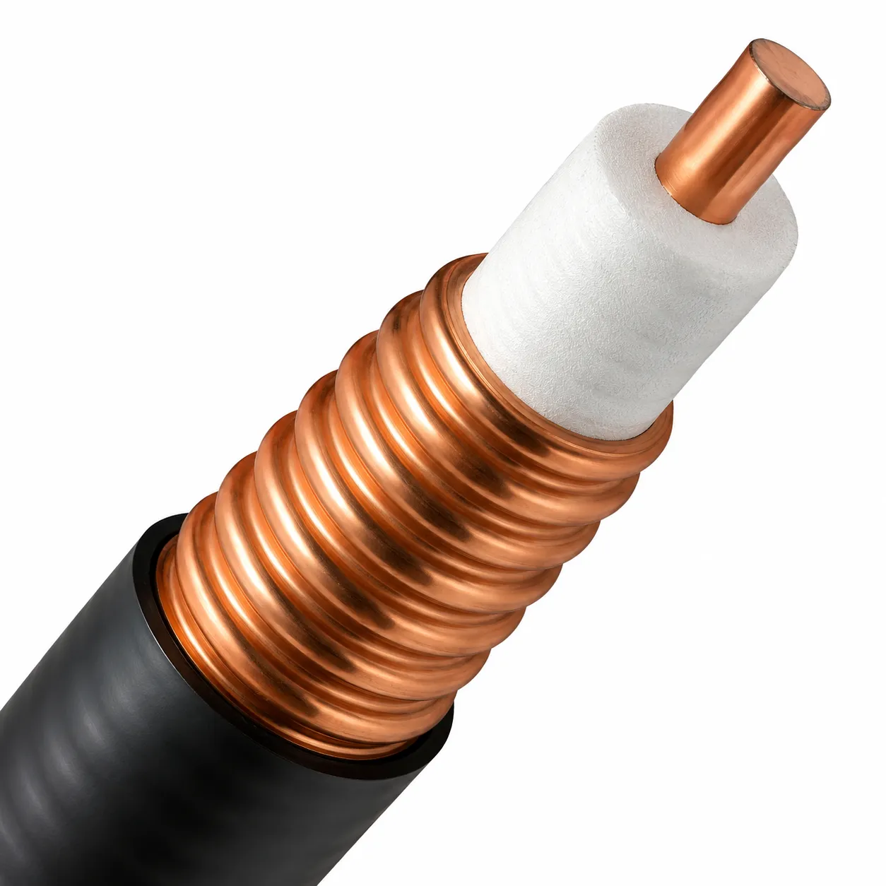
In RF and microwave system design, off-the-shelf components work well when mechanical envelopes, signal paths, cable types, and environmental conditions follow standard reference models. However, standard parts create significant integration barriers when projects face restricted enclosure clearance, non-standard cable exit angles, complex impedance transitions, or strict quality verification mandates. For B2B procurement teams and RF system designers, partnering with an ODM RF component supplier transforms these technical bottlenecks into controlled design specifications rather than high-risk field compromises.
Evaluating an ODM RF connector manufacturer requires looking beyond initial unit pricing. Long-term production reliability, cross-batch manufacturing consistency, strict drawing revision control, and rapid Design for Manufacturability (DFM) reviews dictate total project success. A supplier-led ODM program integrates the connector housing, dielectric insulator, center pin contact, cable termination process, and quality testing into a single engineered solution.
1. Converting Complex Application Constraints into Buildable RF Interfaces
Selecting off-the-shelf RF coaxial connectors typically starts with picking an interface family (SMA, N-Type, BNC, TNC, 7/16 DIN, 4.3-10) and gender. An ODM engineering review starts much earlier by defining operational variables:
-
Frequency Spectrum & Bandwidth: What is the maximum operating frequency (e.g., DC to 6 GHz, 18 GHz, or 40 GHz)?
-
Impedance Continuity: Must the line maintain 50-ohm or 75-ohm characteristic impedance across all transitions?
-
Physical Mounting Envelope: What are the exact panel thickness, bulkhead clearance, and outer dimensions?
-
Environmental Exposure: Will the assembly encounter high vibration, salt spray, thermal cycling, or IP67/IP68 submersion requirements?
Because RF coaxial connectors form an unbroken transmission line, physical fit alone does not guarantee performance. An ill-fitted cable termination geometry, incompatible plating material, or abrupt inner-conductor transition introduces impedance discontinuities that degrade system efficiency. Through custom RF connector design, engineers resolve these conflicts before tooling or pilot production begins, locking down the specification via official 2D/3D engineering drawings and First Article Inspection (FAI) reports.
-
Application Constraints: Define operational frequency, spatial limitations, and environmental exposure.
-
DFM Engineering Review: Evaluate mechanical geometry, dielectric selection, and plating materials.
-
Locked Configuration Record: Issue approved engineering drawings and validate First Article Inspection (FAI) samples.
-
Mass Production & Quality Control: Execute production routing under statistical process control.
Key physical benefits achieved through custom RF connectors include:
-
Custom Body & Flange Geometries: Right-angle exits, low-profile housings, and custom 2-hole or 4-hole flange configurations designed for cramped enclosures.
-
Optimized Cable Termination: Precision crimp rings, solder cups, or direct-solder interfaces matched to flexible, semi-rigid, or corrugated cable constructions.
-
Enhanced Mechanical Durability: Heavy-duty coupling nuts and high-cycle beryllium copper (BeCu) contacts built for repeated mating environments.
-
Traceability & Packaging: Custom laser marking, batch lot numbering, and anti-static packaging tailored to automated assembly lines.
2. Precision Control Over Signal Integrity Risks
For high-frequency RF coaxial connectors, electrical characteristics directly dictate signal quality. Voltage Standing Wave Ratio (VSWR), return loss, and insertion loss reveal how effectively an impedance transition transmits RF energy without generating internal reflections. International standards such as IEC 61169-1-4:2020 define standardized test methods for these parameters, emphasizing the necessity of agreed-upon test protocols over simple catalog part numbers.
Working with an experienced ODM RF connector manufacturer enables engineering teams to define and control critical electrical variables:
-
Target Frequency & VSWR Limits: Specifying maximum allowable VSWR (e.g., less than 1.15:1 up to 18 GHz) for the complete assembly.
-
Dielectric Material Selection: Choosing high-grade PTFE, PEEK, or air-articulated dielectrics to minimize dielectric absorption and phase drift.
-
Center Pin Plating & Contact Resistance: Utilizing heavy gold plating (30µin to 50µin) over nickel or copper underplates to maintain low contact resistance and prevent oxidation.
-
Test Fixtures & Verification Methods: Calibrating Vector Network Analyzers (VNAs) with custom test fixtures that mirror real-world PCB or cable interfaces.
-
Signal Transmission Path: Energy flows from a 50Ω source into a high-VSWR joint boundary, creating reflected signal loss before reaching the 50Ω load.
The primary engineering objective during ODM collaboration is identifying critical manufacturing tolerances. A capable RF component supplier isolates key dimensions—such as pin insertion depth and dielectric shoulder steps—from non-critical cosmetic tolerances, implementing Statistical Process Control (SPC) on key parameters.
3. Optimizing Mechanical Integrity and Environmental Protection
Field failures in RF systems rarely stem from cosmetic blemishes; they occur when mechanical loading, moisture ingress, thermal stress, or continuous vibration compromise the connector-cable interface. Standard commercial parts designed for benchtop environments fail quickly under rugged outdoor or mobile conditions.
Designing custom RF connectors allows engineers to pair electrical performance with robust physical protection:
| Mechanical / Environmental Challenge | Catalog Connector Compromise | ODM Customization Solution |
| Tight Enclosure Space | Stressed straight cable entry; sharp bend radius | Integrated 90-degree right-angle body design |
| Outdoor Weathering & Moisture | Standard thread mating; external heat shrink | IP67/IP68 internal O-ring seals and silicone gaskets |
| High Vibration Environments | Standard threaded or push-on coupling | Lock-washer designs, high-torque coupling nuts, or blind-mate snap interfaces |
| Repeated Panel Serviceability | Direct cable soldering; difficult maintenance | Rear-mount bulkhead jacks with custom flat-D panel cutouts |
| Severe Corrosive Exposure | Standard nickel plating; risk of pitting | Passivated stainless steel, Tri-Metal (White Bronze), or specialized plating |
Simultaneously addressing mechanical layout and RF performance eliminates the need for secondary adapters, external weatherproofing boots, or forced cable bend radiuses that degrade performance over time.
4. Reducing Sourcing Friction and Revision Chaos
A major advantage of direct engagement with an ODM RF connector manufacturer like WORLDPEAK is establishing a direct, unmediated communication channel between project engineers, purchasing managers, and factory toolmakers. Instead of cycling unclarified RFQs through distributor channels, direct technical collaboration establishes a single source of truth.
-
Traditional Multi-Tier Sourcing: Buyer -> Distributor -> Sales Agent -> Factory Line (High friction, high risk of miscommunication).
-
Direct ODM Collaboration Model: Buyer Engineering & Procurement -> WORLDPEAK ODM Factory Engineering (Direct technical specs, faster DFM review, locked engineering control).
This direct workflow improves procurement in four distinct ways:
-
Clear, Unambiguous RFQs: Standardized technical packages eliminate guessing, providing an exact basis for tooling cost and unit pricing.
-
Actionable Prototype Samples: Pre-production samples undergo electrical VNA sweeps, mechanical test fitting, and dimensional checks before full-scale manufacturing.
-
Strict Engineering Change Order (ECO) Protocols: Any modification to raw materials, machining tolerances, or plating thicknesses requires formal customer Engineering Change Notices (ECN).
-
Consistent Mass Production: Frozen Bills of Materials (BOM) and documented production routings guarantee that Batch 50 performs identically to Batch 1.
For established product families, maintaining locked drawings and validated FAI records prevents unexpected manufacturing variations across multi-year build cycles.
5. Lifecycle Cost Advantages Over Unit Price Sourcing
Focusing purely on piece-part unit cost leads to higher total cost of ownership when field replacements, labor-intensive installation workarounds, or high factory scrap rates are factored in. While developing custom RF connectors requires an upfront investment in engineering time and custom tooling, it significantly reduces downstream operational expenses.
-
Total Lifecycle Cost Breakdown: Unit Purchase Price + Assembly Labor & Rework + Inline Scrap Rate + Field Failure & Technician Costs = True Total Cost of Ownership (TCO).
By evaluating the complete assembly ecosystem, procurement teams realize substantial savings:
-
Reduced Assembly Labor: Integrated connector features (such as pre-tinned contacts or captive center pins) shorten line assembly times.
-
Eliminated Adapters: Direct custom interfaces remove extra mating points, cutting both material costs and signal loss.
-
Lower Field Scrap Rates: Custom strain-relief mechanisms and robust sealing prevent field failures and warranty claims.
-
Simplified Inventory Management: Replacing multi-part adapter clusters with a single custom connector part number streamlines the supply chain.
B2B Supplier Evaluation Framework for Custom RF Programs
When selecting an RF component supplier for custom development, engineering and procurement teams should audit supplier capabilities using a structured checklist:
-
Engineering Review & DFM Capability: Does the supplier provide full 3D CAD modeling, electromagnetic simulation feedback, and DFM analysis before quoting?
-
In-House Tooling & Machining: Does the facility operate high-precision CNC automatic lathes, Swiss-type turning centers, and dedicated plating lines?
-
Quality Assurance Infrastructure: Are production lots backed by VNA frequency sweeps, plating thickness gauges (XRF), contact resistance testers, and IPX7/IPX8 pressure test chambers?
-
Drawing Control & Change Notification: Is there a formal ECN procedure that guarantees no raw material or geometry changes occur without prior written approval?
An ideal Custom ODM Requirement Package should contain:
-
1. Operating Frequency Band: e.g., DC-6GHz, DC-18GHz, DC-40GHz
-
2. System Impedance Target: 50Ω or 75Ω characteristic impedance
-
3. Cable Type & Stripping Specs: RG-series, LMR-equivalent, semi-rigid, or corrugated
-
4. Mounting Envelope & Flange Dimensions: Panel cutouts, thread pitch, and outer dimensions
-
5. Environmental Sealing Rating: IP67, IP68, or high-vacuum ratings
-
6. Required Test Documentation: VSWR sweep plots, XRF plating thickness, and CMM dimensional reports
Conclusion: Driving RF System Performance Through Tailored ODM Design
Engaging an experienced RF component supplier for custom RF connectors is the most effective approach when electrical performance, mechanical constraints, and manufacturing repeatability must be solved concurrently. Custom ODM engineering converts complex application challenges into locked, reproducible manufacturing processes.





