 EN

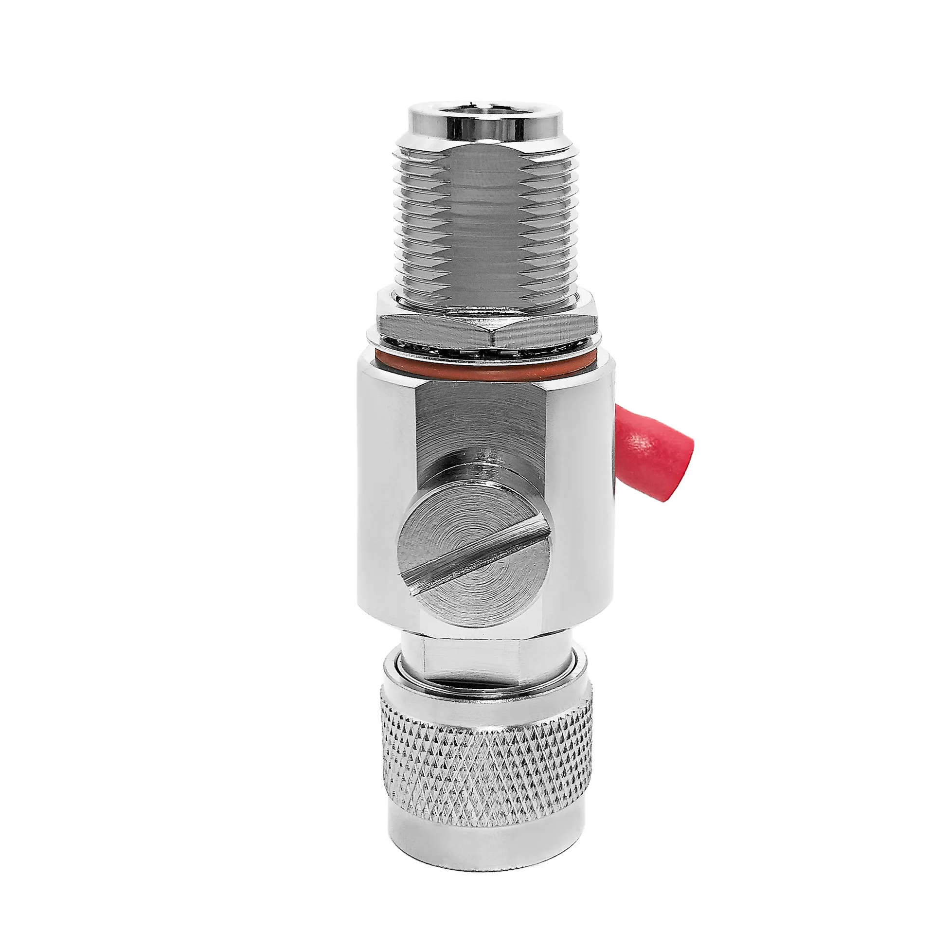
When a procurement manager asks whether an OEM bnc male connector can be "certified," the answer requires a technical explanation rather than a generic claim. An RF connector can be designed, manufactured, tested, and documented to comply with several distinct standards and customer qualification plans. The exact certification framework depends on the interface geometry, nominal impedance (50 Ohm vs. 75 Ohm), cable substrate, contact materials, and destination market regulations.
A catalog description stating that a bnc male connector is "compatible with standard BNC interfaces" does not prove that the delivered part has passed First Article Inspection (FAI), lot traceability reviews, or material testing. Compliance must be treated as a structured qualification plan supported by documented engineering evidence.
Separating Interface Standards from Product Certification
The standard BNC interface is a bayonet-coupled RF coaxial connector family engineered for rapid mating and reliable RF signal transmission. For an OEM bnc male connector, an international interface specification serves as the baseline because it defines mating dimensions, pin geometries, dielectric tolerances, and electrical boundaries.
-
IEC 61169-8 Specification: Defines the physical interface dimensions and basic electrical expectations for RF coaxial connectors with bayonet lock (type BNC).
-
Defense & Aerospace Standards: Military supply chains frequently reference MIL-PRF-39012 or MIL-STD-348 alongside customer source-control drawings.
-
Interchangeability vs. Verification: An interface standard guarantees physical mating compatibility, but it does not automatically certify that an OEM bnc male connector meets specific plating thickness, pull-force limits, or thermal shock cycles required by a regulated program.
Core Certification Groups for OEM Programs
To establish a defensible qualification plan, an OEM program must categorize compliance across four distinct standard groups:
| Standard Category | Primary Reference Standards | Key Test & Verification Parameters | Required Documentation Deliverable |
| 1. RF Interface & Performance | IEC 61169-8, MIL-STD-348 | Impedance (50/75 $\Omega$), VSWR limits, Insertion Loss, Screening Efficiency | VNA Frequency Sweep Reports |
| 2. Military & High-Rel Programs | MIL-PRF-39012, Customer SCDs | Contact retention, Dielectric Withstanding Voltage (DWV), Plating thickness (Gold/Nickel) | Lot Traceability & FAI Reports |
| 3. Material & Regulatory | EU RoHS (2011/65/EU), REACH (EC 1907/2006) | Substance limits (Pb, Cd, Hg, Cr VI, PBBs, PBDEs), Phthalate compliance | Bill of Materials (BOM) & Material Declarations |
| 4. Environmental Sealing | IEC 60529 (IP Ratings), MIL-STD-202 | Thermal shock, Humidity cycling, Salt spray corrosion, Cable retention | IP67/IP68 Environmental Validation Reports |
A 50-ohm bnc male connector and a 75-ohm version feature different pin and dielectric dimensions to prevent impedance mismatches. Verifying compliance requires mapping specific test protocols directly to the selected part number.
Testing Verification Path for OEM BNC Assemblies
Process Step Breakdown
-
Raw Material Audit: Verify brass body composition, PTFE dielectric purity, and beryllium copper center contact alloys against material test reports (MTRs).
-
Dimensional Verification: Inspect the bayonet coupling pins, outer spring contact, and center male pin dimensions against IEC 61169-8 mechanical gauges.
-
Electrical Performance Testing: Connect the bnc male connector assembly to a calibrated Vector Network Analyzer (VNA) to record Return Loss (VSWR) and insertion loss up to 4 GHz (for 50 Ohm) or 3 GHz (for 75 Ohm HD-SDI video applications).
-
Environmental & Mechanical Validation: Subject sample lots to cable retention pull tests, bayonet torque tests, and salt spray exposure.
The Myth of Universal BNC Certification
A common misunderstanding in RF procurement is assuming that "if the connector is a standard BNC, it is already fully certified." While the bayonet interface allows different BNC parts to mate physically, mechanical engagement alone does not guarantee electrical performance or environmental durability.
An unverified bnc male connector may fit a front panel jack while exhibiting poor VSWR due to improper cable termination, or fail under vibration due to inadequate bayonet spring tension. Furthermore, when deploying a bnc connector adapter to bridge different connector interfaces (such as BNC-to-N or BNC-to-SMA), the bnc connector adapter must be qualified as an independent assembly. An adapter introduces additional mating faces, dielectric transitions, and potential reflection points that require distinct testing.
Building a Production-Ready Qualification Plan
Before releasing an OEM bnc male connector order to production, implement a structured qualification sequence:
-
Freeze Technical Configurations: Lock the exact OEM bnc male connector gender, nominal impedance, target cable substrate (e.g., RG-58, RG-59, RG-179, or LMR-200), crimp/solder dimensions, and plating thickness.
-
Specify Acceptance Standards: List explicit compliance requirements—such as IEC 61169-8 interface compliance, RoHS material limits, or IP67 ingress sealing—on the engineering drawing.
-
Establish Lot Sampling Procedures: Define whether electrical continuity and VSWR checks are 100% tested or verified via statistical AQL sampling plans.
-
Archive Compliance Records: Maintain lot traceability linking incoming raw materials, plating batch certifications, and VNA test sweeps to the final shipment.
Buyer Documentation Checklist & Sourcing Recommendations
When receiving a certified bnc male connector shipment or bnc connector adapter lot, confirm that your quality control team receives the following deliverables:
-
Revision-Controlled Assembly Drawing: Detailing physical dimensions, material callouts, and plating specifications.
-
Certificate of Conformance (CoC): Signed declaration attesting that the OEM bnc male connector shipment matches the released specification.
-
Material Compliance Records: Official RoHS and REACH declarations covering all metallic, dielectric, and sealing components.
-
RF Performance Sweep Data: VNA test charts demonstrating VSWR compliance across the specified operational bandwidth.
For technical datasheets, certified drawing templates, and high-frequency interconnect solutions, explore the product engineering catalog at





