 EN

A custom coaxial jumper is often simple to describe verbally during initial project discussions, yet surprisingly difficult to manufacture repeatedly from an incomplete engineering drawing. A procurement note specifying merely "50-ohm, two meters, SMA right-angle connector" leaves critical parameters unmanaged. Production teams still require precise callouts for cable shield construction, connector pin depth, clocking angles, reference planes, manufacturing tolerances, labeling conventions, and acceptance criteria.
Missing these core details turns a standard Request for Quotation (RFQ) into rounds of clarification—or worse, results in a delivered coaxial cable assembly that fits physically but fails under real-world operating conditions.
An OEM drawing serves as a legally controlled contract between engineering, procurement, production, and quality inspection teams. This is crucial for a high frequency coaxial jumper, where subtle geometry shifts near the connector interface compromise VSWR performance, phase stability, and mechanical repeatability.
Application Context and Fundamental Electrical Specifications
Place application parameters directly near the title block or in a dedicated drawing notes section. State whether the custom coaxial jumper serves laboratory test instruments, outdoor 5G telecom towers, military radar systems, or dense industrial automation cabinets. While operational context does not replace geometric dimensions, it alerts the rf connector manufacturer to select materials suitable for thermal cycling, vibration, or weather exposure.
CORE ELECTRICAL ACCEPTANCE BLOCK
-
System Impedance: 50 Ohm (DC to 18 GHz)
-
Return Loss (VSWR): ≥ 20 dB (VSWR ≤ 1.22) via Vector Network Analyzer Sweep
-
Insertion Loss: ≤ 0.85 dB (Full Band At 25°C)
-
PIM Rating: ≤ -160 dBc (2x 20W Carriers for Telecom Use)
For a high frequency coaxial jumper, specify the upper frequency threshold alongside the interface series. This allows the manufacturing engineer to verify whether the specified cable and connector combination maintains adequate margin. Avoid copying catalog baseline figures into the drawing unless they represent actual receiving inspection pass/fail gates.
Complete Cable Callouts and Length References
The cable specification forms the core of any coaxial cable assembly drawing. Provide the exact cable part number when mandatory. If substitutions are permitted, define the technical criteria an approved alternative must satisfy:
-
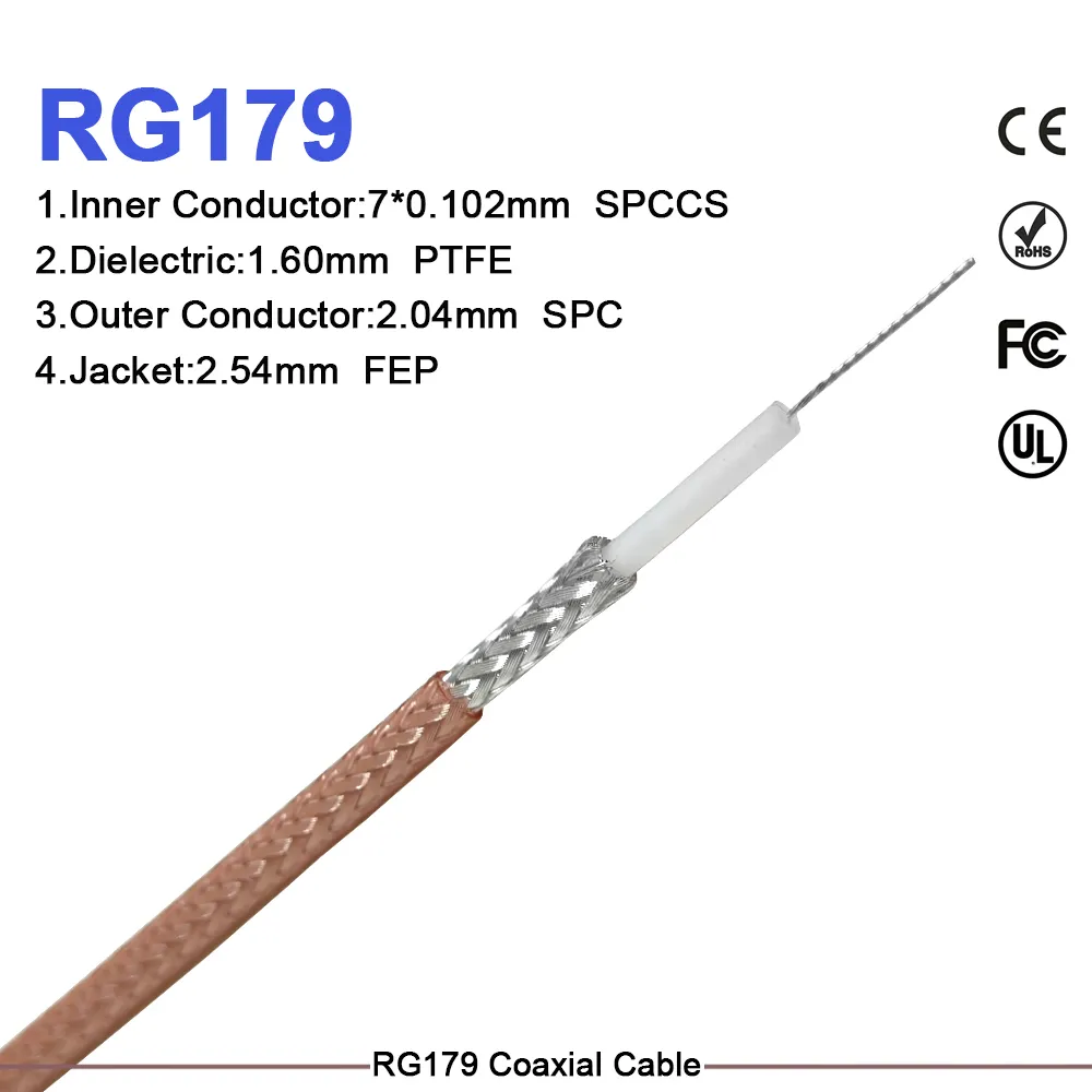
Cable Construction: Specify outer jacket material (e.g., FEP, LSZH, PVC), dielectric structure, center conductor material (solid vs. stranded), and shielding type (braided, foil, or double-shielded).
-
Mechanical Limits: Note the minimum static bend radius and dynamic flex requirements to protect the termination zone.
-
Length References: Clearly define how the overall length is measured. A custom coaxial jumper measured from connector reference plane to reference plane yields a different physical length than one measured tip-to-tip.
-
No-Bend Strain Zones: On a high frequency coaxial jumper, mark a restricted "no-bend zone" directly behind the strain-relief boot to prevent mechanical loading on the soldered or crimped contact termination.
DIMENSIONAL REFERENCE SCHEMATIC Connector Ref Plane (End A) => FINISHED LENGTH (L ± tol) <= Connector Ref Plane (End B) [No-Bend Zone] ---------------------- Cable Body ---------------------- [No-Bend Zone]
Defining Connectors, Clocking, and Mechanical Layouts
Avoid general callouts like "SMA male both ends." Treat each connector end of the custom coaxial jumper as an independent, controlled feature:
CONNECTOR FEATURE SPECIFICATION
-
End A Specification: SMA Male (Plug), Right-Angle, Passivated Stainless Body, Gold Plated Beryllium Pin, MIL-STD-348
-
End B Specification: N-Type Male (Plug), Straight, Tri-Metal Plated Body, Gold Plated Brass Pin, IEC 61169-16
Connector Clocking and Orientation
When a custom coaxial jumper features two right-angle connectors, keyways, or directional boots, state the clocking angle explicitly. Define whether 0° is aligned with the flat, keyway, or cable exit direction, along with the viewing direction (e.g., "looking into End A interface"). If orientation is unconstrained, explicitly note "Clocking Free" on the drawing to prevent production misinterpretations.
Materials, Environmental Ratings, and Traceability
Where operating conditions demand high durability, list specific material requirements on the drawing:
-
Plating and Finish: Specify contact and body plating thickness (e.g., 30µ" gold contacts, tri-metal body) to prevent oxidation, galvanic corrosion, or passive intermodulation (PIM) issues.
-
Weather Sealing: Call out internal O-rings, IP67/IP68 sealing, or heavy-duty adhesive-lined heat shrink for exposed outdoor environments.
-
Traceability and Labeling: Detail part numbers, lot codes, revision levels, and labeling positions. Assign clear "End A" and "End B" designations on both the drawing and physical heat-shrink labels.
Working with an established rf connector manufacturer like
Inspection Gates and Production Acceptance Requirements
The final section of an OEM drawing controls how the completed coaxial cable assembly will be tested and accepted before shipment.
ACCEPTANCE AND INSPECTION MATRIX
-
Visual & Mechanical: MIL-STD-105E / Dimensional Check (100% Visual / AQL 0.65)
-
Electrical Continuity: DC Resistance Test (100% Production Batch)
-
RF Performance: VNA Sweep for VSWR & Insertion Loss (100% Swept High-Freq)
-
Quality Documentation: Certificate of Conformance (CoC Delivered with Shipment)
For a high frequency coaxial jumper, clarify whether 100% vector network analyzer (VNA) sweep testing is required or if a statistical sampling plan applies. Requesting calibration standards, first-article inspection reports (FAIR), or retained sweep data prior to volume release ensures the delivered coaxial cable assembly meets all physical and electrical requirements.
Developing an explicit drawing checklist with an experienced rf connector manufacturer protects your supply chain, eliminates engineering revision cycles, and delivers consistent electrical performance across every production batch.





