 EN

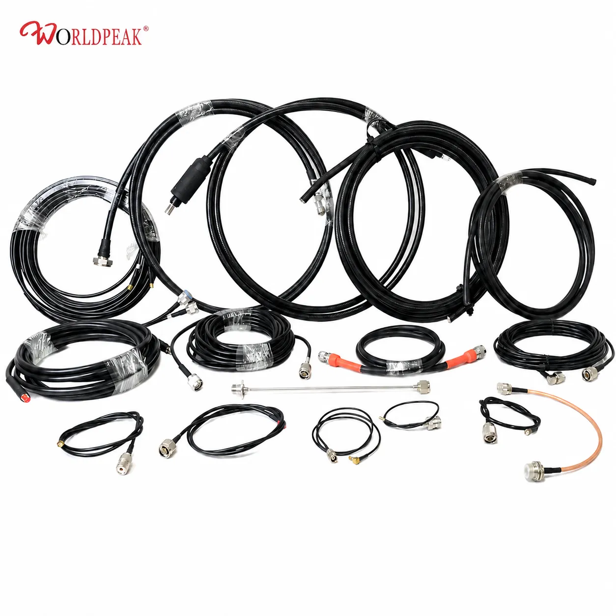
Original Design Manufacturer (ODM) production for an rf connector adapter must never begin with an unverified dimensional drawing alone. An interconnect component that looks mechanically familiar on paper can still introduce unexpected signal reflection, pin contact degradation, rapid plating corrosion, or inspection failures during high-volume assembly. From a procurement and engineering perspective, a well-structured Request for Quotation (RFQ) transforms an intended transmission line into a fully controlled specification package before custom tooling, sample verification, and mass production release.
ODM RF ADAPTER SPECIFICATION WORKFLOW
[Interface & Geometry] > [RF Electrical Window] > [Materials & Plating Stack] [Mechanical & Torque] < [Environmental Tests] < [Quality & Traceability Logs]
The core challenge in ODM manufacturing is not simply asking whether a custom adapter coax design can be machined. The priority is establishing a formal technical agreement on connector interfaces, electrical boundaries, raw materials, RF testing protocols, and lot acceptance criteria. Working alongside a qualified rf connector manufacturer like Worldpeak helps engineering and purchasing teams confirm these parameters early to streamline pilot runs and prevent costly line downtime.
Interface Definitions and Geometry Specifications
Establishing exact interface parameters is the foundational step for custom rf connector adapters. Identifying the basic connector family (e.g., SMA, N-Type, BNC, TNC, 7/16 DIN, or 4.3-10) is necessary, but incomplete on its own.
INTERFACE CONFIGURATION BREAKDOWN
-
Side A Interface: Male (Plug) / Female (Jack) / Standard / Reverse Polarity
-
Side B Interface: Male (Plug) / Female (Jack) / Standard / Reverse Polarity
-
Body Geometry: Straight / Right-Angle / Bulkhead / Flange-Mount
-
Mating Standards: MIL-STD-348 / IEC 61169 Series Compliance
-
Mechanical Limits: Panel Thickness, Keying Way, Clearance Envelope
Always reference a controlled interface standard (such as IEC 61169 or MIL-STD-348). When requesting a non-standard adapter coax combination, explicitly mark which dimensions are fixed and which may be adjusted by the rf connector manufacturer to optimize signal path continuity. This prevents a common procurement issue: a sample that fits a test port but fails to mate with production hardware in the field.
Setting Electrical Operating Windows and VSWR Thresholds
Frequency limits should be specified as a complete operating band rather than a single nominal maximum figure. An rf connector adapter rated for a broad frequency band is not automatically acceptable across every sub-band without verified reflection loss targets.
-
System Impedance: Lock in nominal 50 Ω or 75 Ω continuity across both interfaces and connected cabling.
-
VSWR & Return Loss: Define maximum VSWR or minimum return loss thresholds across the target frequency band. Referencing international standards like IEC 61169-1-4 ties electrical acceptance to standardized measurement methods using a calibrated Vector Network Analyzer (VNA).
-
High-Frequency Testing Points: For a high-frequency adapter coax assembly, require specific test frequency points and sampling quantities to be documented within the quality control plan.
Insertion Loss, Power Handling, and Passive Intermodulation (PIM)
| Technical Parameter | Engineering Boundary Condition | Industry Standard / Test Context | Procurement Risk Mitigation |
| Insertion Loss | Maximum permitted dB loss at operating frequencies | Individual piece test vs. qualified batch sweep | Prevents excessive link budget attenuation |
| RF Power Rating | CW or peak power level under specific thermal environment | IEC 61169-1-6 (Frequency, Temp, Altitude) | Prevents dielectric breakdown and thermal failure |
| PIM Rating | Low-PIM threshold (e.g., ≤ -160 dBc @ 2x 20W) | Mated assembly vs. standalone adapter testing | Eliminates intermodulation interference in 5G |
For high-power telecom infrastructure or broadcasting applications, providing exact duty cycles and environmental conditions allows your rf connector manufacturer to select dielectrics and contact spring materials capable of handling peak RF voltages without thermal runaway.
Materials, Plating Systems, and Corrosion Performance
The material stack dictates mechanical wear cycles, contact resistance, and long-term environmental durability. Never assume visually similar rf connector adapters utilize identical plating thickness or dielectric materials.
MATERIAL & PLATING ARCHITECTURE
-
CENTER CONTACT MATERIAL: Beryllium Copper / Hard Gold Plating
-
DIELECTRIC SYSTEM: Virgin PTFE / High-Temp Hydrocarbon
-
BODY & SHELL FINISH: Passivated Stainless / Tri-Metal Plating
-
ENVIRONMENTAL SEALING: Silicone O-Rings (IP67/IP68 Rated)
When specifying an adapter coax design for outdoor marine, telecom, or transport installations, detail salt-spray exposure hours (e.g., 48-hour, 96-hour, or 500-hour), operating temperature windows (-40°C to +85°C), and vibration limits. Ensure substance compliance guidelines such as RoHS and REACH are explicitly documented in the technical agreement.
Mechanical Reliability, Assembly Controls, and Quality Traceability
To ensure repeatable performance across multiple production lots, distinguish design qualification testing from routine production lot checks:
-
Torque and Engagement Controls: Define mating cycle limits, recommended coupling torque, and body shear resistance. Threaded interfaces require clear torque limits, while push-pull styles require positive engagement retention checks.
-
First-Article Approval (FAI): Require first-article reports covering full dimensional inspection, plating thickness verification, and environmental endurance tests prior to volume release.
-
Lot Inspection & Traceability: Establish pass/fail gates for routine lot checks, including 100% visual inspection, thread gauging, DC continuity, and statistical VNA sweeps. Enforce revision control on all technical drawings, requiring written approval before an rf connector manufacturer can substitute raw materials or plating vendors.
Partnering with an experienced rf connector manufacturer like





