 EN

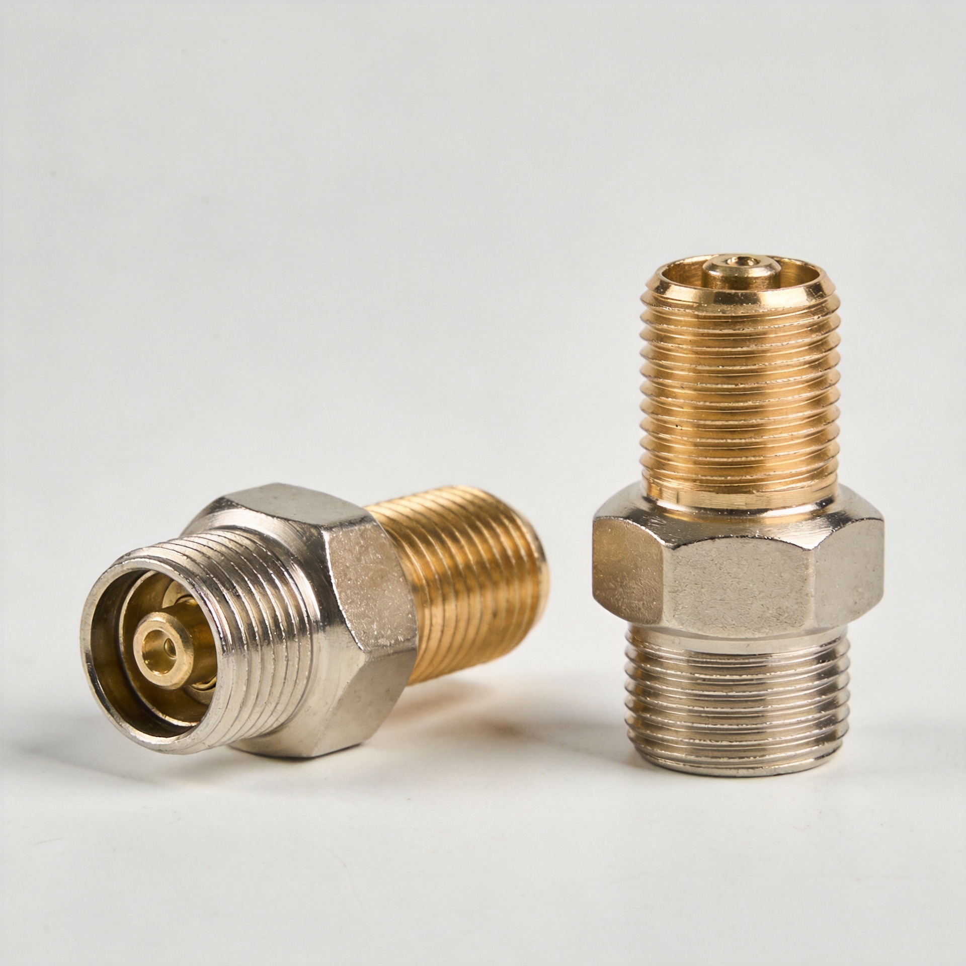
When an RF transmission path fails to mate cleanly on an assembly line or field installation, procurement teams often reach for an off-the-shelf coupler to bridge the gap. While a standard interconnect might solve a immediate mechanical physical issue, it frequently introduces severe electrical degradation down the line. A coax to coax adapter is never just a simple threaded brass shell: it forms a critical transmission junction inside the signal path where interface geometry, contact pinning, dielectric constant, characteristic impedance, operating bandwidth, and enclosure clearances directly dictate system performance.
OFF-THE-SHELF VS CUSTOM RF COUPLING
-
Off-The-Shelf Stack: Port A -> Adapter 1 -> Adapter 2 -> Port B (High Reflection)
-
Custom Direct Path: Port A ==========================> Port B (Minimal VSWR)
For systems integrators and OEM engineers building high-frequency equipment, connector selection determines whether the entire signal chain achieves specified return loss targets. A custom coaxial adapter provides a controlled engineering solution to align dissimilar interfaces, respect tight link budgets, and prevent assembly strain—eliminating the hidden operational risks created by generic catalog components.
The Hidden Compatibility Problem Beyond the Connector Face
Two RF ports can possess interface threads that appear compatible during a manual fit check, yet still constitute a flawed coupling pair. Subtle dimensional variances in pin depth, center contact diameter, or dielectric mating planes can degrade transmission quality. In high-frequency systems, physical mating is only the initial baseline. A coaxial cord adapter must preserve precise impedance continuity across all operating environmental conditions.
INTERFACE EVOLUTION & SELECTION FLOW
-
INTERFACE DIMENSIONAL TOLERANCE: Center Pin Retention & Dielectric Positioning
-
IMPEDANCE CONTINUITY MATCHING: 50-Ohm / 75-Ohm Transmission Baseline
-
MECHANICAL ENCLOSURE FITTING: Right-Angle / Bulkhead Clearance
-
ENVIRONMENTAL & STRUCTURAL SEALING: IP67/IP68 Sealing & Tri-Metal Plating
Specifying a coax to coax adapter requires evaluating the entire cable assembly rather than relying on catalog photographs. For instance, inserting an unverified 75-ohm transition into a 50-ohm system to resolve a gender mismatch causes immediate signal reflections, leading to poor return loss and elevated Voltage Standing Wave Ratio (VSWR). The central design question is not merely whether two ends can be physically screwed together, but whether the complete assembly supports the system's operational bandwidth.
4 Ways Customization Eliminates Interconnect Barriers
1. Direct Interface Matching Without Improvised Stacks
Attempting to connect mismatched gender or connector families using off-the-shelf components often forces engineers to chain multiple couplers together. Every additional mechanical interface introduces contact resistance, potential pin damage, and signal leakage. A custom coaxial adapter combines the required plug/jack configurations into a single, precision-machined housing—eliminating unnecessary junctions and simplifying long-term maintenance inspections.
2. Safeguarding Signal Integrity and Electrical Paths
Every transition within an RF signal chain impacts total attenuation and reflection parameters. A custom coaxial adapter maintains strict impedance matching (50-ohm or 75-ohm) and high-frequency return loss performance. Partnering with an experienced rf connector manufacturer ensures that center contacts, dielectrics, and body tolerances are ground to exact specifications, protecting tight link budgets in sensitive high-frequency applications.
3. Adapting to Real-World Enclosure Geometries
In compact industrial cabinets, outdoor cell sites, and dense test benches, straight interconnects often cause severe cable bending and mechanical stress on internal PCBS. Custom form factors solve these space constraints directly:
-
Right-Angle Bodies: Route cables along cabinet walls to avoid exceeding maximum bend radii.
-
Bulkhead Mounting: Provide secure panel pass-throughs while maintaining environmental sealing.
-
Extended Lengths: Provide necessary hand-clearance inside crowded rack hardware.
4. Engineered for Harsh Operational Environments
Standard catalog adapters built for indoor bench testing fail rapidly when exposed to vibration, moisture ingress, or thermal cycling. A tailored coaxial cord adapter incorporates specialized plating, internal O-ring seals, and robust coupling mechanisms matched to the end-use environment:
| Environmental Demand | Standard Catalog Adapter | Engineered Custom Adapter | Operational Benefit |
| Outdoor / Marine | Commercial Bright Nickel | Tri-Metal (White Bronze) / Passivated SS | Prevents galvanic corrosion and PIM degradation. |
| High Vibration | Threaded Brass Coupling | Beryllium Copper Contacts / Lock-Nut | Maintains center contact retention force. |
| Washdown / IP Rating | Unsealed Threaded Interface | Dual Internal Silicone O-Rings (IP67/IP68) | Prevents moisture ingress into internal dielectrics. |
| High Mating Cycles | Low-Cost Gold Flash (<100 cycles) | Hard Gold Plating 30µ"-50µ" (1000+ cycles) | Preserves low contact resistance over repeated use. |
Practical RFQ Specification Checklist for Custom Adapters
To turn an ambiguous "adapter required" inquiry into an engineering-ready specification package, provide your chosen rf connector manufacturer with complete technical parameters:
-
Interface Definitions: Detail both connector families (SMA, N-Type, BNC, TNC, 7/16 DIN, 4.3-10), genders (plug/male, jack/female), and thread polarity requirements.
-
Electrical Constraints: State nominal system impedance (50-ohm / 75-ohm), operating frequency range (e.g., DC to 18 GHz), and maximum acceptable VSWR / insertion loss thresholds.
-
Mechanical & Form Factor Limits: Specify body geometry (straight, right-angle, bulkhead, flange-mount), spatial clearance envelopes, cable routing direction, and required mating cycle ratings.
-
Environmental Conditions: Detail indoor or outdoor exposure, IP sealing requirements, operating temperature windows, and mechanical vibration levels.
-
Quality Verification: Request vector network analyzer (VNA) sweep reports, dimensional inspection logs, and plating thickness verification certificates.
Evaluating Standard vs. Custom Interconnect Investments
Standard catalog couplers remain a cost-effective choice for low-risk, indoor bench applications where physical clearances are generous and electrical margins are wide. However, when project requirements involve dissimilar connector families, crowded enclosures, high vibration, or strict return loss targets, specifying a custom coaxial adapter prevents expensive field failures and assembly rework.
COMPONENT SELECTION DECISION FLOW
-
Is installation space restricted?
-
YES: Select Custom Right-Angle / Bulkhead Geometry
-
NO: Proceed to Step 2
-
-
Are mating interfaces non-standard or mismatched?
-
YES: Specify Custom Adapter
-
NO: Standard Catalog Adapter is Sufficient
-
Reliable interconnect compatibility requires defining requirements before hardware arrives at the installation site. Collaborating directly with an established rf connector manufacturer like





