 EN

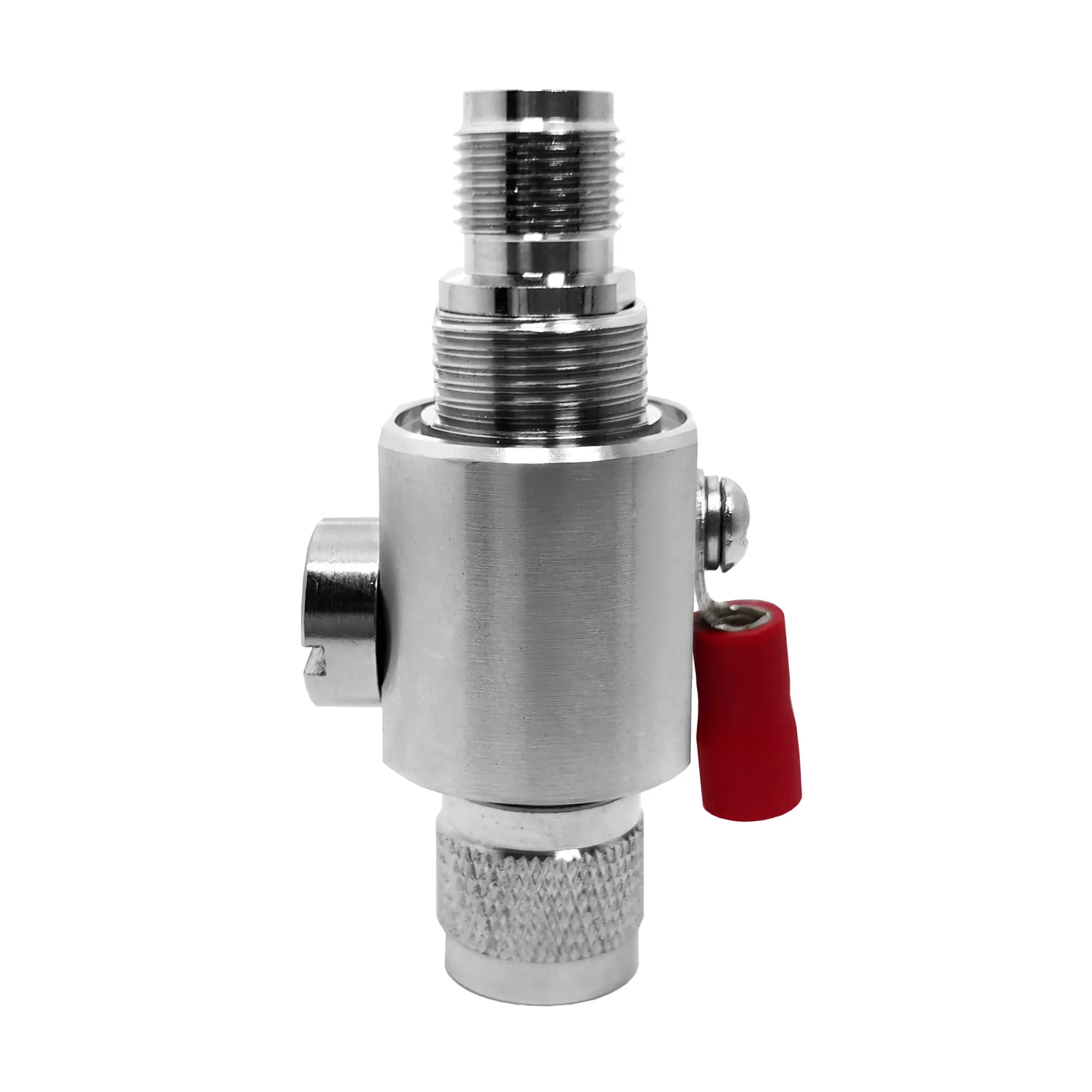
When an original design manufacturing order transitions from technical drawings to mass production, small mechanical and electrical mismatches can lead to costly factory rework. For a precision tnc female connector, conducting a rigorous sample verification phase serves as the critical gateway between receiving a quotation and establishing a controlled manufacturing baseline. A datasheet alone cannot serve as a production baseline; physical prototype evaluation is required to guarantee signal integrity, mechanical threading, and dielectric stability across high-volume production runs.
Whether sourcing individual components or complete assemblies incorporating a tnc to sma connector adapter, buyers must evaluate real-world samples under actual operating conditions. Engaging in comprehensive sample verification allows engineering, quality assurance, and procurement teams to validate critical parameters before thousands of units inherit subtle design flaws. Partnering with a specialized manufacturer like WORLDPEAK ensures every custom tnc female connector satisfies strict tolerance limits, impedance stability, and environmental sealing standards.
Why Datasheets Cannot Replace Physical Sample Verification
RF coaxial interfaces combine high-frequency electrical geometry with complex mechanical features. While a tnc female connector may be cataloged as a standard 50-ohm component, real-world variations exist across center contact retention, crimp ferrule geometries, dielectric materials, body plating, and reverse-polarity configurations. Relying solely on a part number or quotation sheet exposes procurement teams to significant risk during volume production.
Common Failure Modes Identified During Prototype Testing:
-
Polarity Discrepancies: Inadvertently mixing standard polarity and reverse-polarity (RP-TNC) pin configurations.
-
Thread and Coupling Friction: Mismatched thread pitch or poor body plating resulting in binding during mating.
-
Cable Termination Misalignment: Incorrect ferrule crimp dimensions leading to cable pull-out or high reflection.
-
Impedance Continuity Spikes: Microscopic gaps between dielectric seating and center contacts creating VSWR spikes at target frequency bands.
Executing a structured sample verification protocol eliminates these variables early in the development cycle, locking down technical specifications before committing to full production tooling.
Technical Comparison: Standard vs. Reverse Polarity TNC Female Interfaces
Understanding structural variations is essential when conducting a sample verification review. The table below outlines key mechanical and application distinctions across common tnc female connector configurations and adapters.
| Parameter | Standard TNC Female Connector | Reverse Polarity (RP-TNC) Female | TNC to SMA Connector Adapter | High-Frequency TNC Female |
| Center Contact Gender | Female Jack (Receptacle Socket) | Male Pin (Plug Pin inside Jack Housing) | Dual Interface (TNC Jack to SMA Plug/Jack) | Precision Air-Dielectric Socket |
| Outer Threading | 7/16-28 UNEF Mating Thread | 7/16-28 UNEF Mating Thread | Dual Standard Threading | Precision Extra-Fine Thread |
| Nominal Impedance | 50 Ohm (Optional 75 Ohm) | 50 Ohm | 50 Ohm | 50 Ohm |
| Operating Bandwidth | DC to 11 GHz | DC to 6 GHz / 11 GHz | DC to 12.4 GHz – 18 GHz | DC to 18 GHz |
| Dielectric Material | Solid PTFE | Solid PTFE | High-Density PTFE / PEEK | Air / PTFE Support Ring |
| Primary Applications | Cellular Infrastructure, Industrial Radios | Wi-Fi Access Points, Consumer Wireless | Test Equipment, Cross-Band Links | Defense Radar, Aerospace Bench Testing |
Four Pillars of a Comprehensive Sample Verification Protocol
To ensure repeatable performance across production batches, engineering teams should structure their sample verification plan around four essential evaluation pillars:
1. Interface and Polarity Confirmation
Verify outer housing dimensions, gender, center contact alignment, and thread specifications. When testing a tnc to sma connector adapter, inspect both mating ends independently to ensure proper clearance, pin depth, and retention force when coupled with actual field cables.
2. Workmanship and Material Inspection
Examine body finish (nickel or tri-metal plating), center contact gold coverage, dielectric seating, and strain relief construction. For pre-assembled cables, confirm that the ferrule crimp profile matches the specific coaxial cable jacket and braid construction.
3. Electrical Sweep Testing
Request full S-parameter sweep reports generated on calibrated Vector Network Analyzers (VNA). Compare measured Return Loss (VSWR) and Insertion Loss (dB) against application target bands rather than accepting generic catalog claims.
4. Mechanical and Environmental Durability Testing
Subject the sample to repeated mating cycles, specified coupling torque limits, temperature variation, and vibration. For outdoor installations, perform IP rating ingress checks to verify internal O-ring seal performance under exposure.
How Sample Approval Prevents Mass Production Drift
Establishing a formal sample verification sign-off prevents subtle design changes from being introduced during volume production. Once a prototype unit passes physical, mechanical, and electrical testing, it should be designated as an approved golden sample and locked against a revision-controlled drawing package.
Key Steps for Maintaining Production Traceability:
-
Retain Golden Samples: Store physical, signed reference samples at both the buyer's quality laboratory and the ODM factory.
-
Issue Sample Approval Notification (SAN): Document baseline drawing revision levels, BOM line items, and electrical test boundaries.
-
Establish Engineering Change Order (ECO) Rules: Require formal written notification and re-qualification before any supplier modifies raw materials, plating processes, or sub-tier vendors.
-
First-Article Lot Inspection: Perform comprehensive 100% first-lot inspection matching the approved sample verification baseline before accepting bulk shipments.
OEM Procurement Checklist Before Mass Production Release
Before authorizing mass production of any custom tnc female connector or tnc to sma connector order, complete the following quality control checklist:
-
Cross-Check Latest Drawing Revision: Confirm CAD drawings, BOM items, and sample labels share matching revision letters.
-
Conduct Mating Tests on Actual Hardware: Mate the tnc female connector to intended field units rather than shop test gauges.
-
Confirm Test Frequency Bands: State explicit VSWR and insertion loss limits across the full operational bandwidth.
-
Lock Material and Plating Specifications: Specify body base metals (brass or stainless steel) and plating thickness standards.
-
Partner with a Certified Manufacturer: Working directly with an established supplier like WORLDPEAK gives buyers access to factory-direct engineering support, lot-level VNA test reports, and fully traceable tnc female connector production lines.





